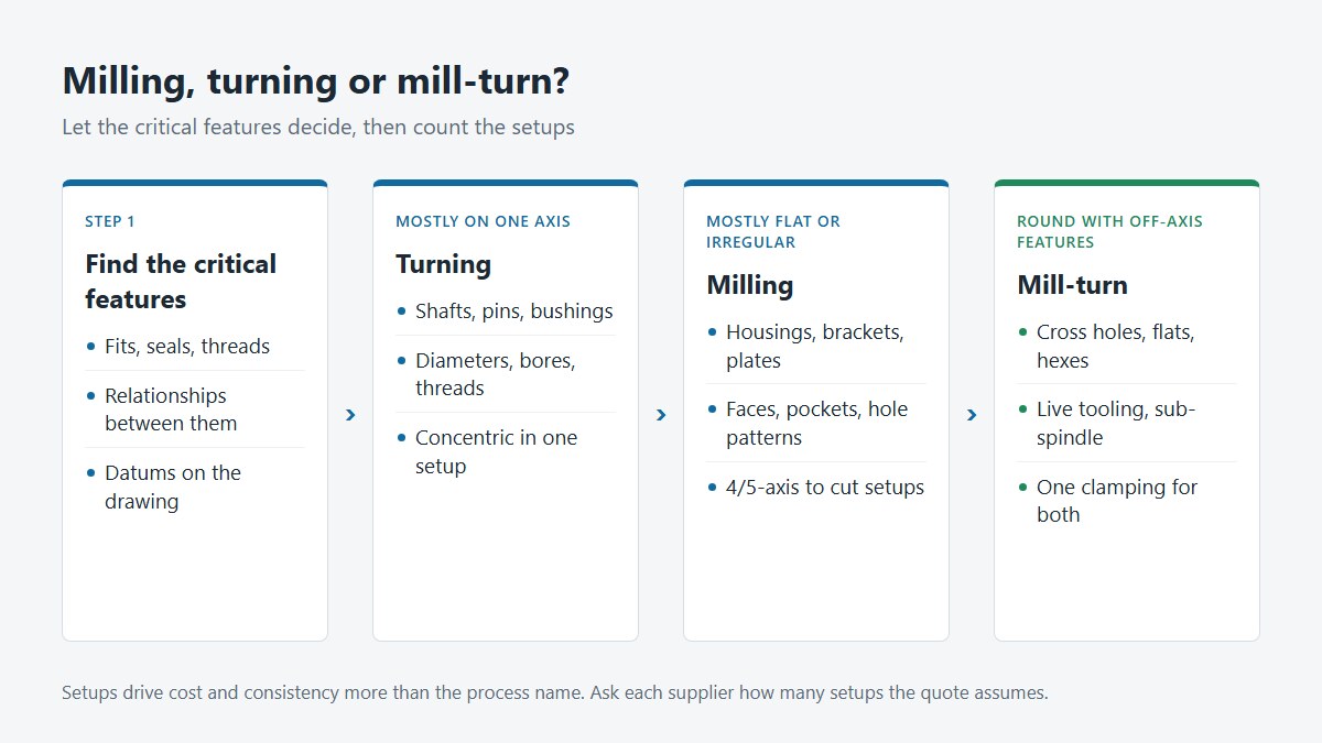
The short answer: turning is for parts that are mostly round, and milling is for parts that are mostly flat-sided or irregular. In turning, the workpiece spins and a stationary tool cuts it. In milling, the tool spins and moves across a workpiece that is held still. Most real parts are not purely one or the other, so the useful question is not "milling or turning?" but "which features drive the process, and how many setups will the part need?"
This guide explains how each process works, how to read a drawing for clues, when a mill-turn machine is the better answer, and how the choice shows up in cost and lead time.
Key Takeaways
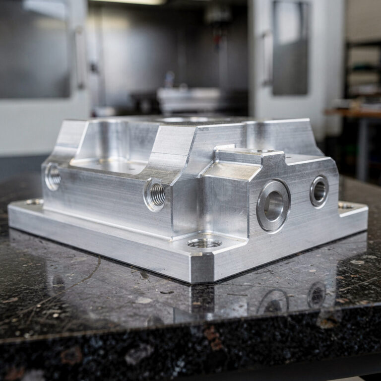
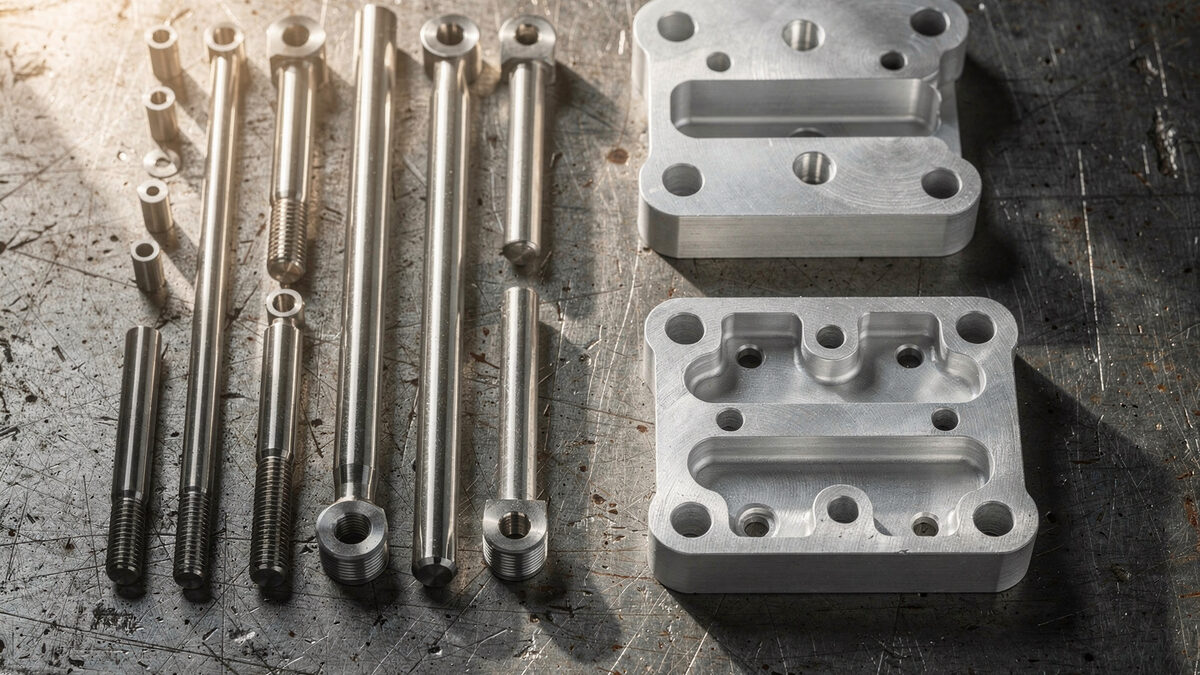
- Turning suits parts built around one axis: shafts, pins, bushings, sleeves and fittings. Milling suits prismatic and irregular parts: housings, brackets, plates and manifolds.
- Features that share an axis (diameters, bores, shoulders, threads) are easiest to keep concentric when they are turned in one setup.
- Flats, cross holes and slots on a round part can often be made on a mill-turn machine with live tooling, avoiding a second machine and a second setup.
- Setups drive cost more than the process name. A design that needs fewer setups is usually cheaper and more consistent.
- Put the process decision on the drawing indirectly: show datums and the relationships that matter, and let the supplier choose the route.
How Turning Works
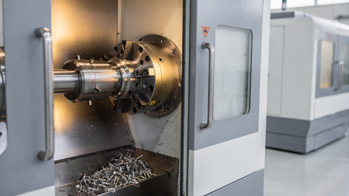
On a CNC lathe, bar stock or a blank is held in a chuck or collet and rotated. Cutting tools move along and across the rotating part to produce diameters, faces, grooves, tapers, bores and threads. Because every turned surface is generated around the spindle axis, features made in the same setup share that axis naturally. That is why turning is the usual choice when concentricity and roundness matter.
Swiss-type lathes are a variant for long, slender parts. The bar is supported close to the cutting point by a guide bushing, which limits deflection on small diameters. They are common for small precision pins, screws and medical components.
How Milling Works
On a CNC milling machine, the workpiece is clamped in a vise or fixture, and a rotating cutter moves in three or more axes to remove material. Milling produces flat faces, pockets, slots, steps, holes, contours and 3D surfaces. With a 3-axis machine, each side of the part generally needs its own setup. With 4-axis and 5-axis machines, the part can be rotated or tilted so that several sides are reached in one clamping. Our guide to 5-axis CNC machining explains when that is worth it.
Milling handles almost any shape, but internal corners between walls have a radius at least equal to the cutter radius, and deep, narrow features need long tools that limit reach.
Reading the Drawing: Which Features Point Where
| Feature on the drawing | Usually points to | Why |
|---|---|---|
| Several diameters on one axis | Turning | Generated around the spindle, concentric in one setup |
| Internal bore with tight fit to an OD | Turning | Bore and OD cut without re-clamping |
| External or internal threads on the main axis | Turning | Thread cut on the lathe |
| Grooves, undercuts, O-ring seats on a diameter | Turning | Formed with grooving tools |
| Flat faces on several sides | Milling | Each face is a milled surface |
| Pockets, slots, steps | Milling | Need a rotating cutter moving in X/Y |
| Hole patterns on a face | Milling (or live tooling) | Positioned drilling |
| Cross holes or flats on a round part | Mill-turn, or turning plus milling | Off-axis features on a turned body |
| 3D contoured surfaces | Milling, often 5-axis | Need simultaneous multi-axis motion |
If most of the critical features are in the top half of the table, start from turning. If most are in the lower half, start from milling. If the critical features are on both sides of the table, look at mill-turn.
When Mill-Turn Is the Better Answer
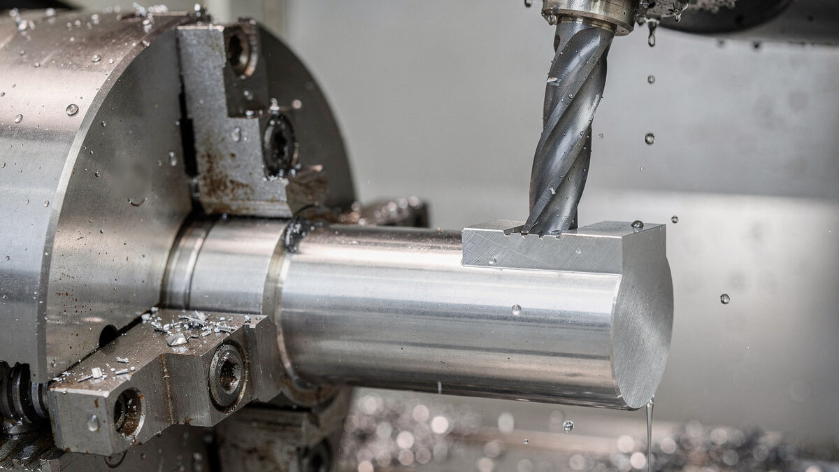
A mill-turn machine is a lathe with live tooling: driven tools in the turret that can mill and drill while the spindle is stopped or indexed. Some machines add a sub-spindle that picks up the part to work on its back side.
Mill-turn makes sense when a round part has off-axis features that must relate to the turned ones, such as a cross hole that must be square to the bore, a flat that sets the orientation of a thread, or a hex on the end of a shaft. Doing everything in one clamping avoids moving the part to a mill, so the relationship between turned and milled features is not affected by a second setup.
It is not automatically cheaper. Mill-turn machine time costs more than a simple lathe, and programming takes longer. For low quantities with loose relationships between features, turning followed by a short milling operation can be the better route. For production quantities, or where the off-axis features must locate precisely from the turned ones, mill-turn usually wins.
How the Choice Affects Cost and Lead Time
The process name matters less than the number of setups, the cycle time and the stock used.
- Setups. Each time a part is re-clamped, there is setup time and a chance of location error. Designs that let critical features be made in one setup save both.
- Stock. Turned parts usually start from round bar close to the finished diameter, so little material is removed. A round part milled from a square block wastes material and time.
- Cycle time. Turning removes material quickly on round shapes. Milling pockets and contours takes longer, especially with small cutters.
- Quantity. Bar-fed lathes run unattended for long periods, which makes turning very efficient for repeat production of small round parts. Milling is often more efficient for low quantities of complex shapes.
When you compare quotes, ask each supplier how many setups they plan and on which machines. Two quotes that look far apart are often based on different routes.
Design Tips for Each Process
For turned parts
- Keep critical diameters, bores and threads on the same axis, and dimension them from a common datum axis.
- Add a thread relief or undercut where a thread runs up to a shoulder.
- Avoid very long, thin sections without support. Long slender parts deflect under the cutting force unless they are made on a Swiss-type lathe or supported.
- Use standard bar sizes for the largest diameter where possible.
For milled parts
- Give internal corners a radius. A larger radius allows a larger, stiffer cutter.
- Limit pocket depth relative to width. Deep, narrow pockets need long tools and slow cutting.
- Keep walls thick enough to resist vibration and distortion.
- Put features on as few sides as practical, and use consistent datums across views.
For mixed parts
- Decide which features are critical to each other, and show those relationships on the drawing with datums and geometric tolerances.
- If a flat or cross hole only needs to be roughly positioned, say so. A loose relationship can be made on a separate machine at lower cost.
Common Mistakes
- Specifying the process instead of the requirement. Writing "turned" on a drawing can rule out a better route. State the geometry and tolerances, not the machine.
- Tight concentricity across two setups. If a bore and an outside diameter must be concentric but cannot be turned together, expect higher cost or ask for a design change.
- Milling a round part from a block. If the part is essentially round, a turned blank with milled features is usually faster and uses less material.
- Sharp internal corners on milled pockets. They need EDM or special tools. A radius is usually acceptable.
How Othala Approaches Process Selection
We review the drawing and model before quoting, identify the critical relationships, and choose the route with the fewest setups that will hold them. If a design change would reduce setups or cost, we note it in the quote. Inspection uses CMM, optical inspection and gauges as the features require. Our quality management system is certified to ISO 9001:2015 and ISO 13485:2016.
See our CNC milling services, CNC turning and 5-axis CNC machining pages.
Frequently Asked Questions
Is turning more accurate than milling?
Not in general. Turning makes it easier to hold roundness and concentricity on features that share an axis, because they are cut in one setup around the spindle. Milling holds positional relationships well between features on flat faces. The achievable tolerance depends on the feature, material, size and setup, not only on the process.
Which is cheaper, milling or turning?
For round parts, turning is usually cheaper because it starts from bar close to size and removes material quickly. For prismatic parts, milling is the natural choice. Cost depends mostly on the number of setups, cycle time and quantity.
Can one machine do both?
Yes. Mill-turn machines combine a lathe with live tooling, and sometimes a sub-spindle, so many round parts with flats, cross holes or slots can be finished in one clamping.
Should I specify the process on my drawing?
Usually not. Specify the geometry, datums and tolerances that the part needs, and let the supplier choose the route. If you have a reason to require a process, explain it in a note.
What is Swiss turning used for?
Swiss-type lathes support the bar close to the cut, which suits long, slender and small-diameter parts such as pins, screws and medical components.
Conclusion
Turning is the natural process for parts built around one axis, and milling for flat-sided and irregular parts. Many parts need both, and the best route is the one that makes the critical relationships in the fewest setups. Show those relationships clearly on the drawing, leave the machine choice to the supplier, and ask how many setups each quote assumes.
Request a DFM Review
Not sure whether your part should be milled, turned or made on a mill-turn machine?
Send us your 2D drawing, 3D model, material, quantities and critical tolerances. Our engineering team can review the routing and suggest changes that reduce setups and cost. See our CNC machining services or request a quote.