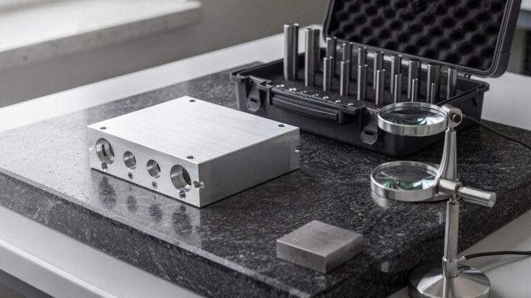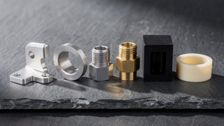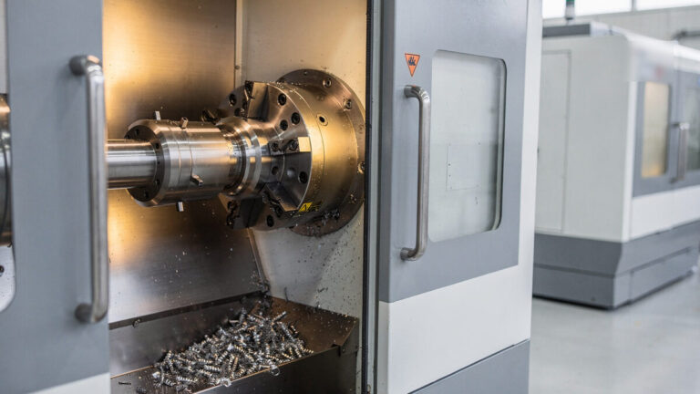
5-axis CNC machining is useful when tool access and relationships between features make a simpler machining route awkward. Angled bores, contoured surfaces and features on multiple faces are common reasons to consider it. The extra axes let the tool approach the workpiece from different orientations, often reducing the need to reposition the part.
The useful question is which features need that access, and whether indexed machining would be enough. Start with the drawing, the functional datums and the surfaces that must relate to one another. Then compare the proposed setups, inspection plan and finishing sequence.
Key Takeaways
- Separate simultaneous 5-axis cutting from indexed positioning before comparing machining routes.
- Fewer setups can reduce relocation error, but do not remove every source of dimensional variation.
- Specify functional relationships and inspection requirements before choosing a machine.
- Keep tool access, fixture clearance and the final unclamping operation in the review.
What Makes 5-Axis Machining Different
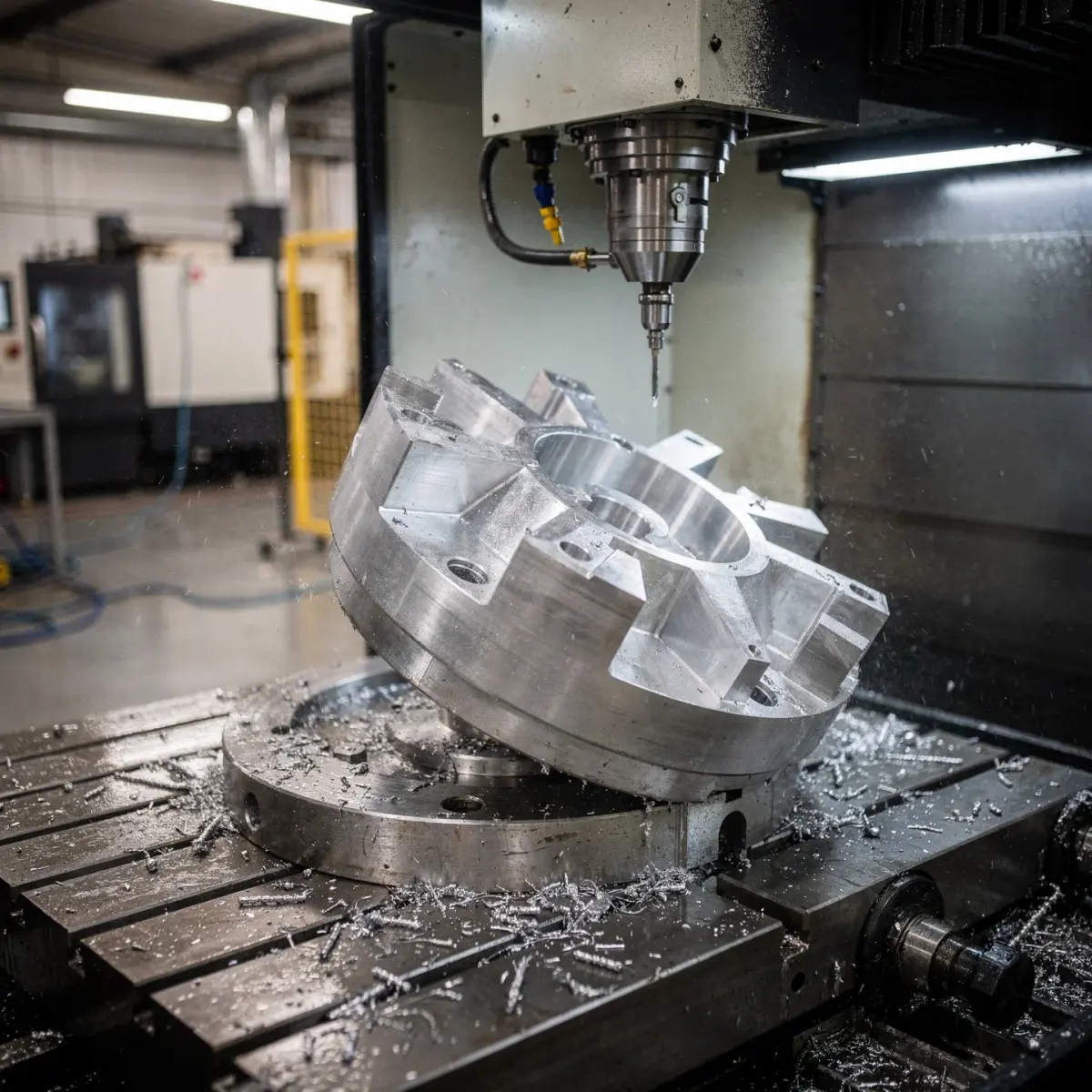
A standard 3-axis CNC mill moves the tool relative to the workpiece along X, Y and Z. A 5-axis machine adds two rotational axes, commonly labeled A and B, or A and C, depending on the configuration. Those rotations change the cutting orientation, but the machine still has travel limits and physical obstructions.
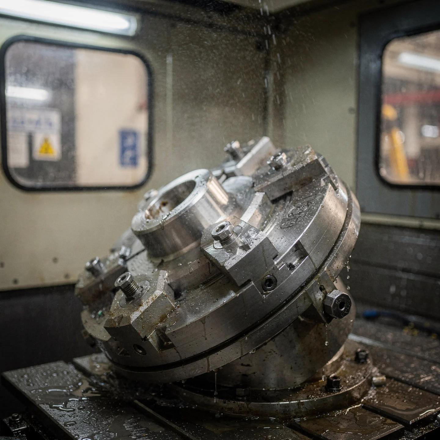
Indexed machining: position, then cut
In indexed machining, often called 3+2 machining, the rotary axes position the part or tool before cutting at a fixed orientation. This can suit angled holes, mounting faces and pockets distributed around a housing. A part may need several cutting directions without needing the tool angle to change continuously during each cut.
Simultaneous machining: change orientation during the cut
Simultaneous 5-axis machining coordinates linear and rotational motion while cutting. It can help follow a changing surface or maintain useful cutter contact along a contour. It also requires a suitable toolpath, machine configuration and collision checks. A contoured part does not automatically require simultaneous motion on every surface.
Why Setup Count Matters
Every time a part is removed from a fixture and re-clamped, there’s a chance for small positional errors to creep in. Keeping related features in one clamping can reduce errors caused by relocating the workpiece. That is particularly useful when angled bores or mounting faces must relate closely to a common datum.
It does not remove machine error, tool deflection, thermal effects or distortion when the clamps are released. The underside of a part may still need another operation because the fixture covers it. Ask which critical features share a setup and how the supplier will locate the part for any remaining cuts.
Consider a bracket with an angled bore and a mounting face. Cutting both without relocation may simplify their relationship. If the drawing instead controls the bore from a face finished later, the process must preserve that relationship through the later operation. Count the setups around the functional datums, rather than counting machine axes alone.
Where 5-Axis Machining Is Actually Worth It
5-axis isn’t automatically the right call for every part. For simple prismatic geometry, a 3-axis mill is often a practical starting point. Extra orientation becomes useful when it improves access, reduces difficult fixture changes or lets critical features be machined together.
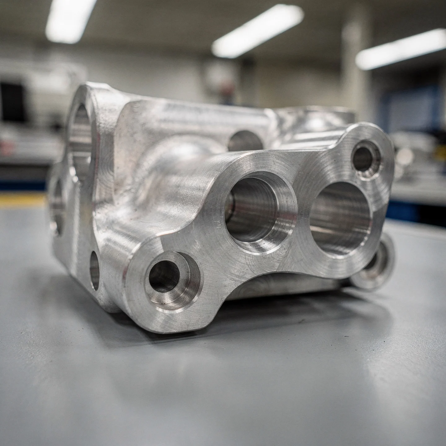
- Compound angles or contoured surfaces that require changing cutting directions.
- Close positional relationships between features on different faces.
- Thin walls or delicate geometry for which repeated clamping needs careful control.
- Complex housings, impellers or structural brackets with restricted tool access.
| Part requirement | Route to evaluate | Question before approval |
|---|---|---|
| Flat plate with accessible pockets | 3-axis milling | Does another orientation add any useful access? |
| Several angled mounting faces | Indexed 3+2 machining | Can each feature be cut at a fixed orientation? |
| Contour needing changing cutter orientation | Simultaneous 5-axis machining | Can the cutter and holder clear the entire path? |
| Round body with cross holes | Turning plus milling or mill-turn | Which route preserves the important axial relationships? |
Compare complete routes, including programming, fixtures, deburring and inspection. A higher-capability machine can reduce handling, while a simpler route may remain appropriate for accessible geometry. For the underlying process choice, see CNC milling vs turning.
Materials and Tolerances
Material, geometry and support determine how a part responds during cutting. Aluminum, stainless steel and titanium require different cutting strategies; none makes a drawing tolerance automatic. Long tools can deflect, thin walls can move, and residual stress can affect shape as stock is removed.
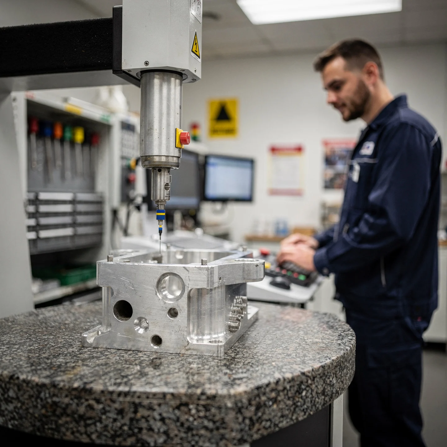
Do not use the machine’s axis count as a tolerance specification. Distinguish the size of a bore from its location, orientation and relationship to a mounting face. A bore can meet its diameter requirement while its axis is misplaced. Give each functional requirement an appropriate datum reference and acceptance method.
State whether dimensions apply before or after finishing. Coatings and other finishing operations can change functional surfaces, so the machining allowance and masking plan need to follow the final requirement. Confirm the proposed tolerance feature by feature after reviewing size, depth, wall thickness and access.
Tool Access and Common Design Mistakes
Assuming rotation makes every surface reachable
The cutter, holder, spindle and fixture all need clearance. A reachable point in the CAD model may still be blocked by the holder or the clamping arrangement. Show undercuts and deep recesses clearly, and ask whether they require a different cutter, another setup or a design change.
Leaving sharp corners and deep pockets unexplained
Rotating milling cutters leave radii in internal wall corners. Deep, narrow pockets can require longer tools with less rigidity. Identify where corner relief is acceptable and where a mating component needs clearance. A slightly different pocket shape may simplify machining without changing the assembly interface.
Using the same tight tolerance everywhere
Separate bearing seats, locating holes and sealing faces from clearance surfaces. Blanket tight tolerances add machining and measurement work even where assembly does not need it. Keep the critical relationships explicit, and use general tolerances for features whose variation does not affect function.
Getting Started
If you’re not sure whether your part needs 5-axis machining or would be better served by 3-axis or turning operations, submit the requirements for a route review. Ask the supplier to explain what the extra axes achieve on your particular geometry.
- Provide a revision-matched 3D model and dimensioned 2D drawing, with units identified.
- Specify material grade and condition, quantities and the intended assembly function.
- Mark datums, critical geometric relationships, threads and surface-finish requirements.
- Identify coating, masking, edge-break and burr-removal requirements at mating features.
- Define the dimensional report, sampling basis and any assembly checks required for acceptance.
For a useful quote comparison, request the intended setup sequence and any proposed drawing changes. Separate a supplier’s suggested relaxation from the released drawing. If you accept a change, revise the controlled document before manufacture so inspection uses the same requirement as production.
Frequently Asked Questions
Is 5-axis machining always more accurate than 3-axis machining?
No. It can reduce errors associated with moving a part between fixtures, but accuracy also depends on machine condition, tooling, workholding, temperature and inspection. An accessible feature on a well-planned 3-axis route may meet the same requirement. Compare the actual feature relationships and process plan.
Does an angled hole need simultaneous 5-axis machining?
Often it does not. Indexed positioning may orient the hole for a conventional drilling or milling operation. Simultaneous motion becomes relevant when the cutting direction needs to change along the path. Tool clearance and the surrounding geometry still need review.
Can every face be finished in one setup?
No. The fixture must hold the workpiece somewhere, and those contact areas may need a later operation. Travel limits and collisions can also restrict access. Ask which surfaces remain unfinished after the main setup and how their relationship to the finished datums will be maintained.
Should I require 5-axis machining on the drawing?
Specify the geometry, material, datums and acceptance criteria first. If a particular process is a contractual requirement, state the reason. Otherwise, allow the supplier to propose a route and explain how it will meet the drawing, including any separate turning or finishing operations.
Related Articles
- 5-axis CNC machining services
- A to Z About CNC Machining
- Titanium vs Steel for Machining
- CNC part inspection requirements
Request a DFM Review
Send Othala Tech your drawing, model, material, quantities and critical feature relationships for a machining review. Include finishing and inspection requirements so the route can be assessed against the completed part. Request a DFM review and quote.